How to run Super Mario Bros on Xiaomi Mi band 4
Everything can execute your code if you try hard enough.
One day, I was cleaning and found my old fitness tracker, a Xiaomi Mi Band 4. In principle, it is a wearable computer, with a battery, display, sensors, and Bluetooth. Can we run something on it? Unfortunately, I am not a security researcher, and I don't program in C for ARM devices. But maybe the current generation of LLMs could help me run something interesting on it? For example, a NES emulator that could play Super Mario Bros with touch controls and keyboard controls over Bluetooth? To me, all of this sounds like science fiction. It would probably take me a year of focused effort. But at least we can try.
Firstly, let's find firmware for it. Luckily for us, it is available on the internet
These are the specs for Xiaomi Mi Band 4:
| Component | Specification |
|---|---|
| Main processor | Dialog/Renesas DA14697, Arm Cortex-M33 with floating-point unit, up to 96 MHz. |
| Bluetooth processor | Separate Cortex-M0+ controller core, integrated 2.4 GHz radio and antenna connection. The band exposes Bluetooth 5.0 LE. |
| Sensor coprocessor | Sensor Node Controller, SNC, which can acquire sensor data while the main CPU sleeps. |
| Working RAM | 512 KiB SRAM |
| Instruction cache | 16 KiB, supporting execution directly from external flash. |
| Internal ROM / OTP | 128 KiB ROM and 4 KiB one-time-programmable memory. |
| External storage | 16 MiB serial NOR flash |
| Display | 0.95-inch AMOLED, 120 × 240 RGB, adjustable brightness. |
| Screen touch controller | Zinitix capacitive-touch controller |
| Front button | One capacitive touch button for wake/back. |
| Wear detection | Capacitive skin/contact sensing; firmware identifies Azoteq IQS620 |
| Accelerometer | Three axes |
| Gyroscope | Three axes. Firmware supports Bosch BMI260 or ST LSM6DSO manufacturing variants |
| Optical heart-rate system | Green illumination LEDs, photodetection, and TI AFE4900 optical analog front end identified in firmware |
| Vibration | ERM/rotor vibration motor |
| Battery | 135 mAh rechargeable lithium-polymer cell. |
Our firmware version is 1.0.9.66.
How do we talk to it? Before the first use of the device, it asks us to use the Mi Fit app (Zepp Life). But why?
The answer is cloud pairing:
-
The band sends a random value and a public-key fingerprint to the app over Bluetooth.
-
The app and the band derive the same key:
D = SHA256(band_MAC_bytes || 16-byte_random) # 32 bytes auth_key = first 16 bytes of D -
Zepp Life asks the cloud to sign
D. It sends the full 32 byte digest (D) and the public-key fingerprint, and receives a signature from the server.After that, it sends this signature to the band.
-
The band verifies the signature.
Ghidra shows
0x616c → 0x2fefcperforming ECDSA-secp256k1 verification against the band's trusted public key:ECDSA_verify(trusted_public_key, D, signature)If verification succeeds, you proceed forward.
-
After you confirm the pairing, the band stores the key.
After that, for each connection:
-
The band sends a fresh random challenge (a random 16-byte value).
-
The app responds with
AES-128-ECB(auth_key, challenge). -
The band computes the same result using its stored key. If they match, it grants access to protected operations.
If you have a rooted Android phone, you can extract this key from the app after cloud pairing is complete. It is stored in: /data/data/com.xiaomi.hm.health/databases/origin_db_*
Here is what we can do with auth_key:
| Operation over BLE | Requires auth_key? |
|---|---|
| Discover the band, connect, list services | No |
| Read serial number and hardware/firmware version | No |
| Read battery information | No |
| Read the band's current clock | No |
| Read current step count | Yes |
| Start/stop heart-rate measurements and receive measurements | Yes |
| Start/stop raw sensor streaming | Yes |
| Download recorded activity/health history | Yes |
| Change personal settings, alarms, goals, units, DND, display/wrist settings | Yes |
| Set date/time | Yes |
| Send text/call notifications | Yes |
| Make the band vibrate / find the band | Yes |
| Send weather and forecasts | Yes |
| Send music title, artist and playback state | Yes |
| Control workout/session state | Yes |
| Upload firmware, watchfaces, resources or fonts | Yes |
The firmware we downloaded is signed, and the updater checks its signature. We could always break open the device (it does not open cleanly, it's waterproof) and flash the memory directly, but we could also try to do it over Bluetooth. If we could find a way to run our own code remotely, over Bluetooth, then we could patch the firmware from the inside. We could disable signature verification and then freely flash modified firmware using the standard DFU mechanism. Dreams...
Or is it actually possible? Although the firmware is signed, it is not encrypted. Therefore, we can decompile it using Ghidra. I asked Codex to map all the surfaces in the firmware that process input received over Bluetooth. Some of the most interesting findings were concentrated around uploading firmware, resources, fonts, and watchfaces.
| Entity | What it contains | What updating it changes | Update type |
|---|---|---|---|
| Firmware (.fw) | Executable code: Bluetooth handling, authentication, sensors, menus, rendering logic | How the band operates; its firmware version | 0x00 |
| Watchface (.bin) | A clock-screen design: images, digits, and layout information | The installed watchface's appearance | 0x08 |
| Resources (.res) | Shared graphical assets used by the interface, such as icons and screen artwork | Graphics used across the band's interface | 0x02 raw; 0x82 compressed |
| Fonts (.ft) | Character glyphs used to draw text | Available characters and how text looks | 0x01 |
But which of these can we actually control? We dont have the private key (it's on the servers somewhere)
| Upload | Signature verified by band? | File verification |
|---|---|---|
| Firmware (0x00) | Yes, ECDSA | HMF trailer/header checks and signature verification |
| Watchface (0x08) | No | CRC32 compared with the uploader-provided CRC |
| Resources (0x02, compressed 0x82) | No | CRC32 compared with the uploader-provided CRC |
| Fonts (0x01) | No | CRC32 compared with the uploader-provided CRC |
I used grok to poke around these surfaces (codex refused) and we found the first bug: Resources are compressed and there is a bug in the code that unpacks them: it could write past the end of its allocated buffer and overwrite other parts of RAM.
How could that let us run our own code?
-
Upload a specially crafted resource update
-
Make the decompressor write beyond its buffer
-
Keep writing until we replace a pointer used by the installer
-
When decompression finishes, the installer uses that pointer to call a function
-
Our replacement pointer sends execution to our code instead
We tried that and initially, the band disconnected a few seconds after we sent the update. It crashed and restarted but we didnt know what exactly happened there. But luckily, we found a useful diagnostic channel in the stock firmware: the band's internal debug log can be downloaded over Bluetooth. On firmware 1.0.9.66, it is exposed as Huami recorded-data type 7 and stored in a roughly 1 MiB circular buffer. Logs are readable text: boot messages, battery and sensor activity, Bluetooth events, update progress, and crash reports.
For example (this is a sample from the log):
[43] hrm_init, mode:0, intv:0
[43] App reboot time 9/9 13:23:58 1.0.9.66
[45] In check_free_region notSynced region=2000->e2000
[45] not synced region=2000->e2000
[45] store_manager_init ==> multi_link is 0
[45] flash id:0xef8018
[45] ==>reset hardfault
[45] R0: 0x2007d242
[45] R1: 0x200210e9
[45] R2: 0x80009801
[45] R3: 0x1
[45] R12: 0x2007d23a
[45] LR: 0xbe2a1
[45] PC: 0xbe286
[45] PSR: 0x1000014
[45] ==>reset hardfault
[45] task: APP_
[45] debug task state:0x0
Once we collected crash logs, we could see what was actually happening:
-
Our first overflow was too long, it kept writing until it reached the end of RAM and then crashed. Also the buffer moved between boots, so the same overflow length did not always stop at the same address
-
Then we tried to shorten it. Now we saw crashes caused by the band's radio processor, its code and data were between our buffer and the pointer we wanted to replace
-
We eventually wrote past the target pointer. This looked promising, but the band crashed before decompression finished, so the installer never used it
-
We stopped the overflow before radio memory. Decompression could finish, but our target pointer remained unchanged. The installer called its normal erase function and erased part of the resources
-
We tried filling radio memory with instructions that loop forever. The hope was that the radio processor would sit in a loop instead of crashing. But it didnt work either
The memory layout looked like this:
Our decompression buffer
         ↓
Radio processor's code and data
         ↓
The pointer we wanted to overwrite
If we wrote far enough to reach the pointer, we destroyed the radio's code and data along the way. If we stopped early enough to avoid that, we never reached the pointer.
After spending some time on this path, I decided to start looking for another one.
Some time passed, and then I had a somewhat unrelated thought: we've seen a lot of vulnerabilities on android, iOS, and others where a specially crafted image could trigger bugs in the image stack, which could lead to memory corruption and code execution. Maybe something like this is possible on this device too?
After the compressed resource vector failed, we tried a different one: a custom watchface, uploaded as type 8 (HMDIAL). Then, after some digging we found another bug, this time in the code that reads BMP images.
The code works like this:
-
Read one row (120 pixels across) of a BMP image into a small buffer
-
Convert those pixels into the screen's color format and paint that line
-
The buffer is reused in the next row
The buffer holds 360 bytes, enough for 120 pixels with three bytes per pixel.
Immediately after the buffer, the firmware stores a pointer to its watchface callback list. This list has three entries, one for each built-in watchface. Each entry points to a record containing five function addresses: drawing, refreshing, cleanup, handling button events, and entering the watchface screen.
But what happens if we upload a 32-bit BMP? Each pixel now takes four bytes, so a row needs 480 bytes. The decoder still copies the entire row into the 360-byte buffer. The extra 120 bytes overwrite the memory after it, including the pointer to the callback list.
We put our own code and callback list into the BMP's pixel data. When the decoder copies those pixels into RAM, it also copies our code. The overflow then replaces the original pointer with the address of our list. When the firmware next uses that list to handle an event, it calls our code.
There is one detail: the band handles built-in and uploaded watchfaces differently. It supports one uploaded watchface, selected with the value 0xfe. For an uploaded watchface, drawing and refreshing use a separate callback record that we haven't changed. But button events and entering the watchface screen still follow the pointer we overwrote, so those events can call our code.
Our plan:
-
Put our functions, a three entry list, and one callback record in the BMP pixels (the same bytes in every row)
-
Let the stock decoder copy each row into that fixed buffer
-
A 480-byte 32-bit row overwrites the cached list pointer just after the 360-byte buffer, and points it at our list
-
Later lookups follow that pointer and call our functions
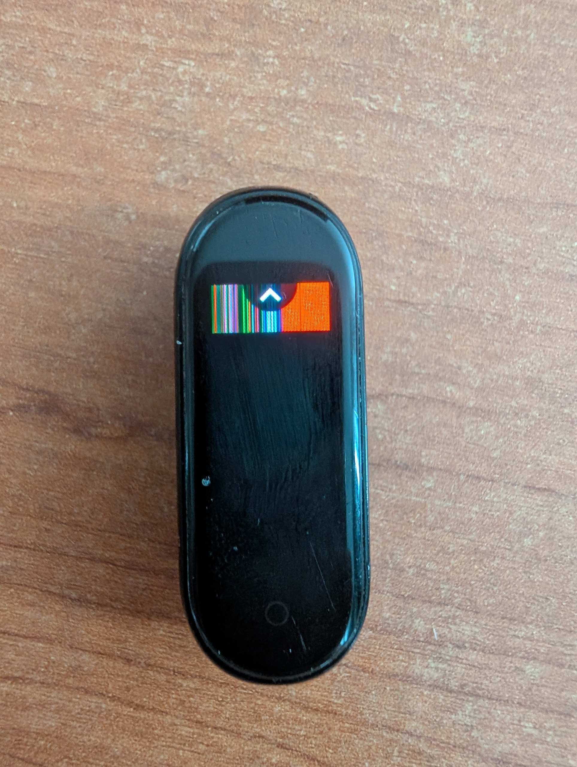
To test whether it then called our code, we used a function that disabled interrupts and counted down before returning. After the custom watchface had been on screen once, pressing the Home button froze the band for about 30 seconds. It recovered, and pressing again repeated the freeze.
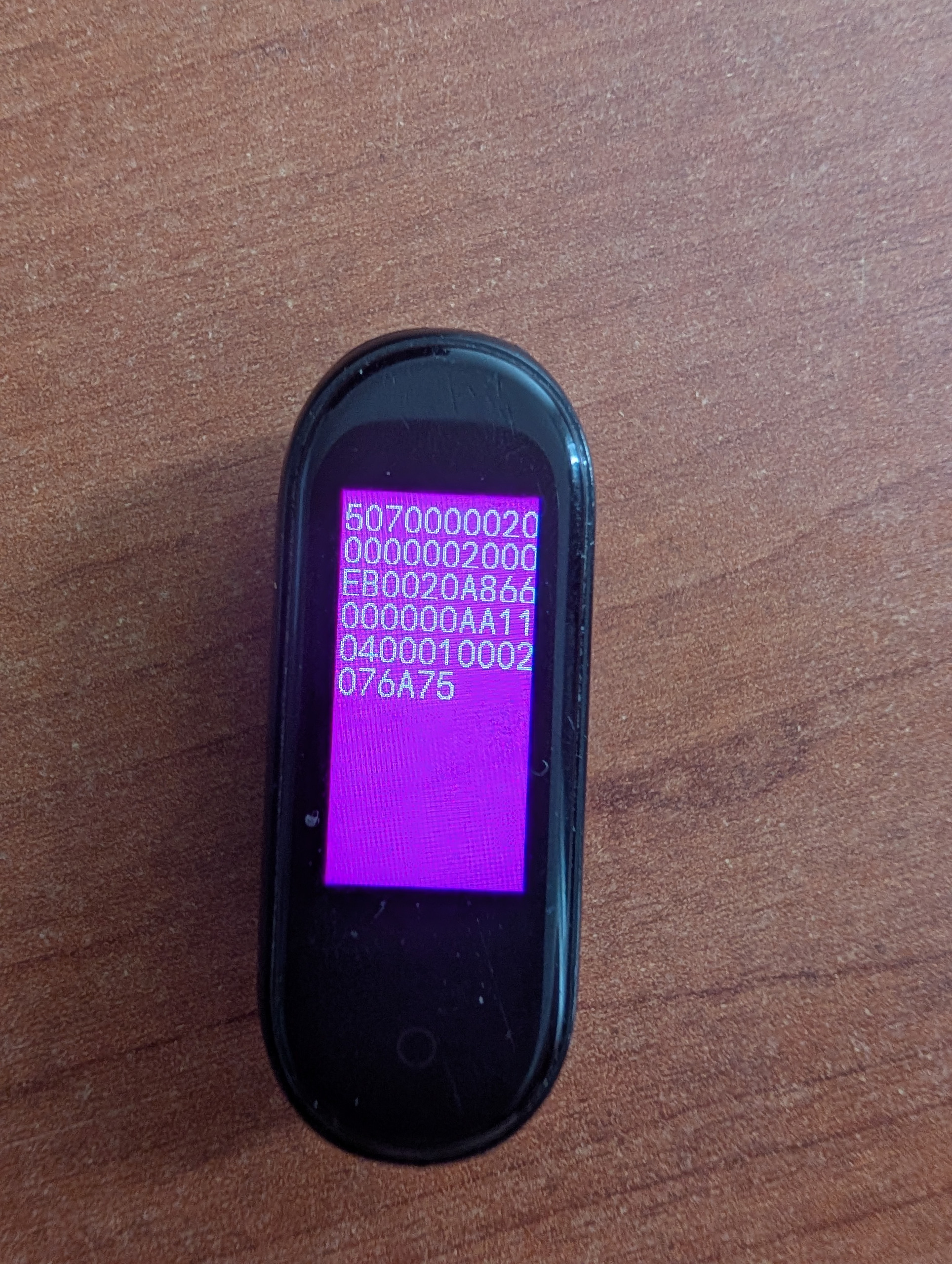
After that, we used the same path to print on the screen various addresses from the firmware, to make sure that all of this was really working. And it really was. We've got our RCE.
Disabling firmware verification
Once we had code execution, now we would like to make it persistent and disable signature verification. This way we could simply use standard firmware update mechanisms.
The band keeps two firmware images in flash, A and B. A boot configuration header (Pp) says which one is active and which one is the last update. When you click update in the mobile app, it sends the firmware to the band's inactive slot, then tells the band to point the header to the new firmware and reboot. We used our RCE to modify the firmware in the inactive slot: we disabled signature verification by simply making it always return success.
Those writes used the firmware's own flash helper, because it already has all the necessary functions: we can get address of a firmware image on the flash and write to it.
We then changed the boot selection and rebooted into the patched firmware in slot A.
With that version running, the normal Bluetooth updater accepted modified firmware. We used it to install another patched copy into slot B, then rebooted again.
Both slots now contained firmware with signature verification disabled. From that point, we could build and install custom firmware through the standard update process, without repeating the watchface exploit.
Custom apps
The existing firmware provides us with operating system (FreeRTOS), graphics library (emWin), and hardware drivers. We want a custom hello world app that could print, for example, free RAM. But how do we even add apps to the firmware binary?
Using Ghidra, we found the functions we needed and figured out how the stock firmware called them. For example, once we know the address of the function that can draw text and which arguments it expected, we can call it through a C function pointer. We can give it a string and coordinates, and let the existing graphics library handle the drawing.
We wrote our app in C, compiled it for the band's ARM processor, and appended the machine code to the firmware image. A linker script assigned addresses to our code and constants. Appending it left the original firmware at its existing addresses, so its internal references still worked. We then updated the image's lengths and checksum and flashed it.
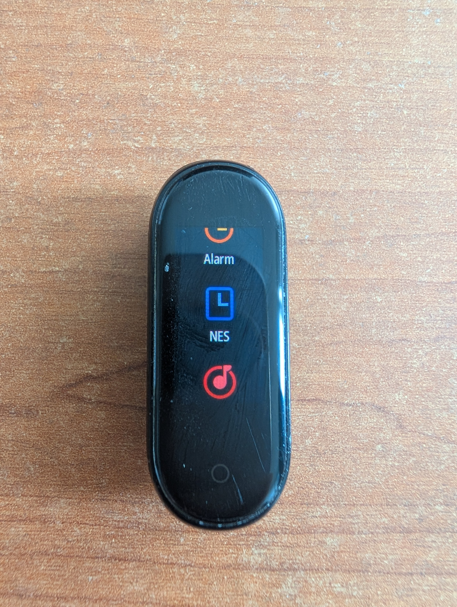
In the code, we found an unused menu record (interestingly, its name is camera_page_create_frame, but we dont have a camera, it seems that they reuse a lot of firmware between different devices), changed its label, and replaced its launcher address with our own function. Tapping the entry now opened our app.
NES emulator
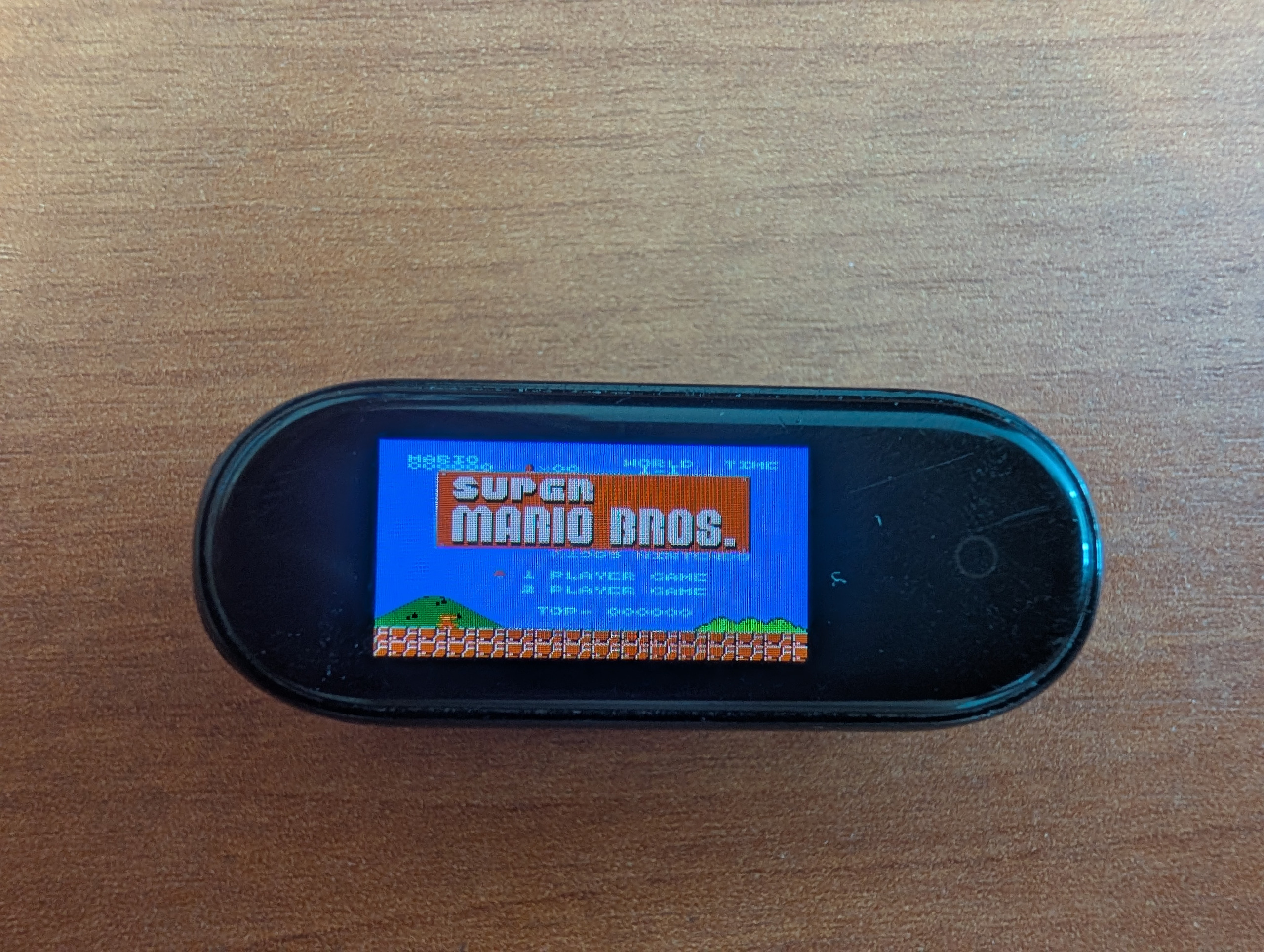
Now that we can run apps, we can start with a NES Emulator. We started from an opensource emulator agnes. At first try, it gave about 5 FPS in Pong, which is not a lot.
We can manually think of the optimizations, apply them and check the difference, but we can also automate it.
This looks like a perfect problem for an llm: we can turn this into a verifiable environment with real hardware testing.
-
we added metrics such as frame rate, time spent drawing and transferring frames, CPU cycles, free memory on the mi band. We store it on the device and sync back to the pc
-
we added a deterministic sequence of inputs and measure metrics on it (it will be our benchmark)
-
To make sure that output didnt change, we created a test set of frames from original agnes emulator that we could compare against. We hash them and compare hashes
-
We keep an experiment log to see what worked and what didnt
-
This optimization loop is fully autonomous and does not require our supervision
The experiment loop looks like this:
-
Benchmark and profile a new change on the PC. We built a partial execution environment around Unicorn, a CPU emulation framework. It ran our compiled ARM instructions, with selected stock and hardware interfaces modeled in Python. We checked results and collected instruction profiles showing which functions and code blocks did the most work.
-
If it is promising, make a new firmware version and update the miband. Later, we added a Bluetooth loader for native ARM code and hooks that let this code replace selected emulator routines. This allowed many optimizations to be tested without reflashing the complete firmware.
-
run it on the real device, get diagnostic data from the real hardware
-
after that we can either add the new change to the current stack of changes, discard it or try to rework it
These are some of the interesting speedups that were found.
Disable screen tearing synchronization
After drawing a frame, we called the stock firmware's display function to send it to the screen. The image lived in a framebuffer in RAM: 120 x 240 pixels, with two bytes per pixel, or 57,600 bytes per frame. The display controller already used DMA, which lets hardware read those bytes from RAM and transmit them without the CPU copying each pixel.
But the transfer did not start immediately. The stock driver waited for a signal from the panel called TE, short for tearing effect. The panel refreshes its visible image progressively. If we send a new frame while the panel is halfway through refreshing the screen, it can show part of the old frame and part of the new one. This is called tearing. The TE signal gives the driver a timing reference for coordinating updates with the panel.
The driver already supported sending a frame without TE synchronization. We found the setting in its configuration structure: a byte at offset 0x3d. We copied that configuration, cleared the byte in our copy, and passed it to the existing driver. With this setting, the driver started the transfer immediately. We still waited for DMA completion before drawing into the framebuffer again, because the controller could otherwise read pixels while we were overwriting them.
In the controlled FPS comparison, mean presentation time fell from 24.93 to 10.10 ms, while drawing stayed almost the same. Across the two Mario scenes, displayed frame rate rose from approximately 19.4 FPS to 27.02 and 25.09 FPS.
The tradeoff was that updates could now happen at a less favorable point in the panel's refresh cycle, but I didn't notice it while playing, so we kept it.
Hot code in RAM
The stock firmware executes much of its code directly from flash, using XIP. We profiled, what 6502 opcodes are the most used in mario and saved the code that emulates them directly to SRAM.
| CPU instruction handlers in SRAM | Scene 240 | Scene 480 |
|---|---|---|
| 0 — CPU interpreter runs from flash | 30.12 FPS | 27.72 FPS |
| 48 — frequently used handlers run from SRAM | 32.06 FPS | 29.74 FPS |
| Improvement | 6.5% | 7.3% |
How to get more RAM?
We added a game boot mode that starts the band with fewer stock services. When entering this mode, the band reboots and follows a modified startup path that skips selected sensor, fitness, calibration, and health-synchronization workers. Avoiding their initialization leaves the memory they would allocate available to the emulator. We kept FreeRTOS, Bluetooth, the display, touch input, storage, and power handling. This helped achieve 84,568 bytes free after starting the emulator. To reboot back to the normal mode, you can press the Home button 2 times.
Double buffering
The stock display path already used DMA, which transfers pixels without requiring the CPU to copy each byte. With one framebuffer, however, the CPU still had to wait before modifying memory the display controller was reading.
We can employ a technique that is called double buffering. While DMA sent frame N from one buffer, the CPU could emulate and draw frame N+1 into the other. Ideally, the frame period moves from roughly render time + transfer time toward max(render time, transfer time), plus scheduling and setup overhead.
Each 120 x 240 RGB565 framebuffer costs 57,600 bytes and this was one of the reasons we needed more ram. With the second buffer allocated, CPU48 improved from 32.06 / 29.78 to 46.68 / 42.10 FPS, roughly 45% faster in the measured scenes.
Direct ROM instruction fetch
The NES has its own memory layout: some addresses refer to RAM, some to the cartridge, and others to hardware registers. Our emulator checked which one it was dealing with whenever it read a byte. That also happened when reading the game's instructions.
But we had already loaded the ROM into the band's RAM. We could find the start of the current 16 KiB chunk of ROM once, then read each instruction directly from that memory. This avoided repeating the same address checks for every byte. Near the end of a chunk, or when running code from NES RAM, we used the full interpreter.
This improved FPS by about 1% and 5% in the two scenes.
For a three-byte instruction, where address is its address in NES memory:
# Before: work out what each NES address refers to
byte1 = read_nes_memory(address)
byte2 = read_nes_memory(address + 1)
byte3 = read_nes_memory(address + 2)

# After: find the ROM chunk once for the group
chunk, start_address = find_rom_chunk(address)

# Then read each instruction directly from that chunk
offset = address - start_address
byte1 = chunk[offset]
byte2 = chunk[offset + 1]
byte3 = chunk[offset + 2]
Optimization results
| Runtime milestone | Mario scene after 240 warmup frames | Scene after 480 warmup frames |
|---|---|---|
| CPU48, synchronous display | 32.06 FPS | 29.78 FPS |
| CPU48, double buffering | 46.68 FPS | 42.10 FPS |
| Batching CPU instructions | 51.20 FPS | 46.14 FPS |
| Direct ROM instruction fetch | 51.70 FPS | 48.84 FPS |
| CPU64 | 55.50 FPS | 51.53 FPS |
| Fused PPU output and color conversion | 57.09 FPS | 53.08 FPS |
Keyboard controller and games library
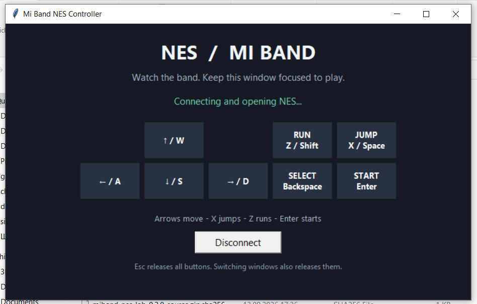
We made a Python app that sends keyboard input to the band over Bluetooth. It tells the emulator which NES buttons are held, and the emulator reads them before running a frame.
During development, the ROM and our accelerated emulator code lived in RAM and disappeared on reboot. We found an unused 512 KiB area in flash and used it to store them, with room for eight games.
Now we can upload a game once, open More → NES, select it, and tap PLAY. The band remembers the selection, reboots into gaming mode, loads the game and emulator code from flash into RAM, and starts playing. Double-tapping Home reboots normally and restores the stock services.
Conclusion
As you can see, with the current tooling, we can achieve things that were previously too time consuming and take control of our own hardware. Next I want to port this project and turn miband into a personal universal tracking device, that support both apple and google services. Seems a little bit more practical than nes emulator, albeit less fun :D
Thanks for reading and go forth and hack!